POWER CORE 6200LFP
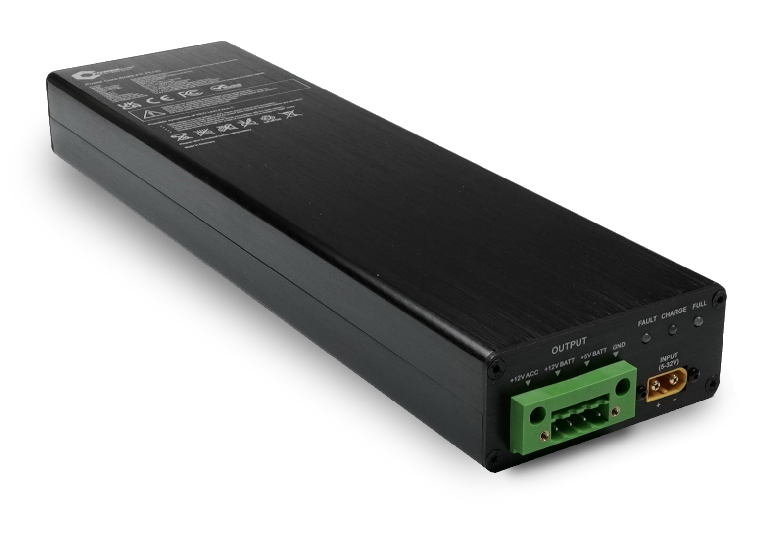
LiFePO4 Quick Charge Power Bank for Dash Camera

⚠ Safety Notice
Before using this device, carefully read the instruction manual included in the package. Improper installation or misuse may cause damage, fire hazard, or serious injury.
Critical Safety Warnings
- Do not expose the device to water, moisture, or fire.
- Do not use the device outside the operating temperature range (-30°C to 70°C).
- Do not strike, throw, drill, crush, or attempt to open the device.
- Do not disassemble or attempt to repair the battery.
- If smoke, unusual smell, or overheating is detected — immediately stop using the device.
Usage & Installation
- Keep away from children and do not allow use without adult supervision.
- Use only appropriate and compatible charging adapters.
- Avoid direct sunlight and keep away from heat sources.
- Ensure correct polarity during installation.
- Keep the device away from loose metal objects to prevent short circuits.
Battery & Storage
- Recharge fully at least once every 6 months if not in use.
- Allow full charge and discharge cycle every 6 months to maintain calibration.
- Store in a dry, ventilated environment.
- Extended inactivity may reduce battery performance.
♻ Disposal
- Dispose of the device at certified battery recycling stations only.
- Do not dispose of the battery in household waste.
Incorrect installation, reversed polarity, or physical damage may cause fire, electric shock, or permanent device failure.
Product Features
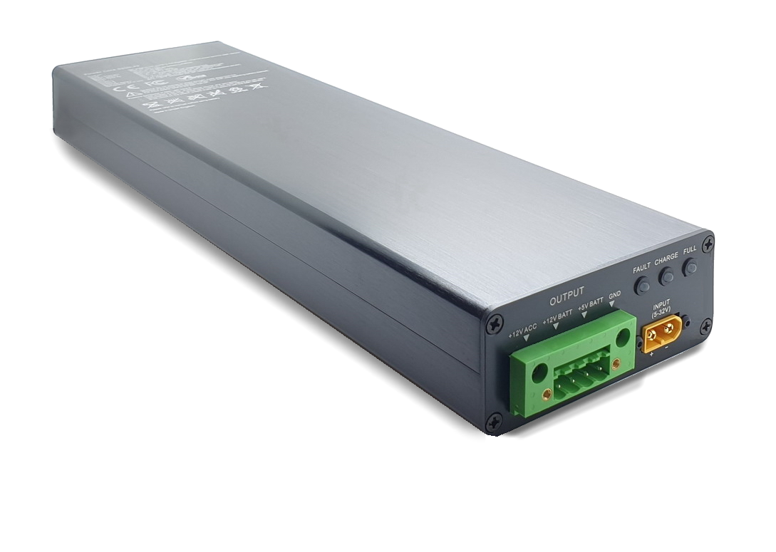
Power Core 6200LFP
Self-Adaptive LiFePO4 Power Bank for Dash Cameras
Performance
- Fast charging: 0–100% in 50 minutes
- 79.36Wh large capacity
- Over 5000+ recharge cycles
- Up to 2 days recording (1CH dashcam)
- Ultra-efficient charging conversion system
- Fully self-adaptive charging circuit
Battery Technology
- LiFePO4 – safest battery chemistry
- 4 high-performance cylindrical cells
- Built-in ultra-efficient 5V converter (Monolithic Power Systems)
- USA Linear Analog Devices chip
- Extendable capacity (external battery module)
Protection & Safety
- Multi-level protection design
- Short-circuit protection
- High & low temperature cut-off
- Reverse voltage protection
- Overcurrent output protection
- Prevents car battery discharge
- No risk of vehicle start failure
Compatibility & Design
- Compatible with 12V cars & 24V trucks
- Works with all dashcams & parking modes
- Easy hardwire installation
- No soldering required
- Full aluminum body
- Manufactured in the UK
Product Specification
General Information
Battery System
Electrical Specification
Output 1: <98%
Output 2: <99%
Output 3: Fused ACC Signal
Performance
Temperature Range
Protection Systems
Certifications
Power Bank Diagram
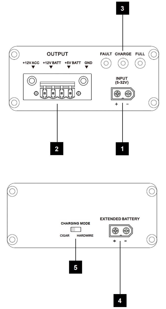
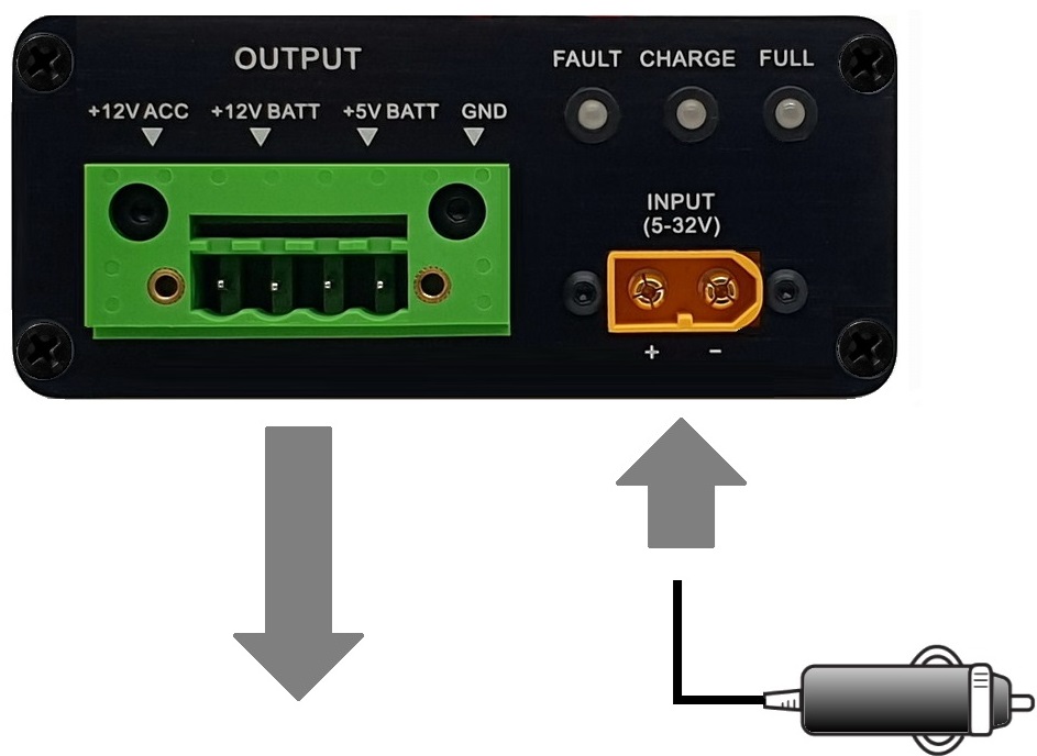
Main power input connector (5V–32V DC).
Multi-output terminal for dashcam and ACC connections.
Charging, fault and full-charge indication.
XT60 connector for additional LiFePO₄ battery module.
Cigar mode (slower charge) or Hardwire mode (fast charge).
Installation Guidelines
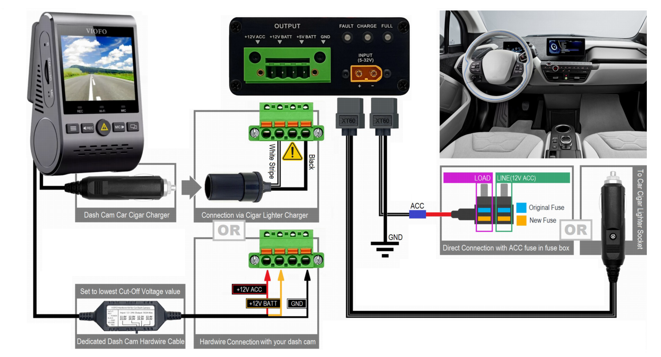
Terminal Connection
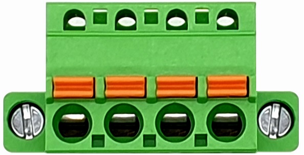
Connect using the dedicated green plug terminal with orange locking buttons. Ensure correct wire insertion and secure locking before powering the unit.
Charging Input
Connect to vehicle power source using either:
- Car cigar lighter socket
- Direct hardwire to fuse box (recommended for fast charging)
Dash Camera – 5V Power Connection
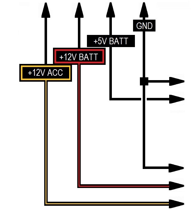
Connect to +5V BATT and GND terminals only.
Dash Camera – 12V Power Connection
Connect to +12V BATT and GND.
+12V ACC (Yellow wire) – Optional ignition signal for dashcams supporting passive parking mode. Ensure parking mode is enabled and low-voltage cut protection is configured correctly.
+12V BATT (Red wire) – Provides backup power to the dash camera when the vehicle is stationary.
Important Installation Warning
Always verify the required voltage of your dash camera before connection. Connecting a 5V dash camera to the 12V BATT terminal may permanently damage the device.
Confirm polarity before powering the system. Use a multimeter to verify voltage and ensure correct positive (+) and negative (–) wiring.
Damage caused by incorrect installation is not covered under warranty.
How to Use the Device
Charging the Power Bank
a) Using the Car Cigar Charger
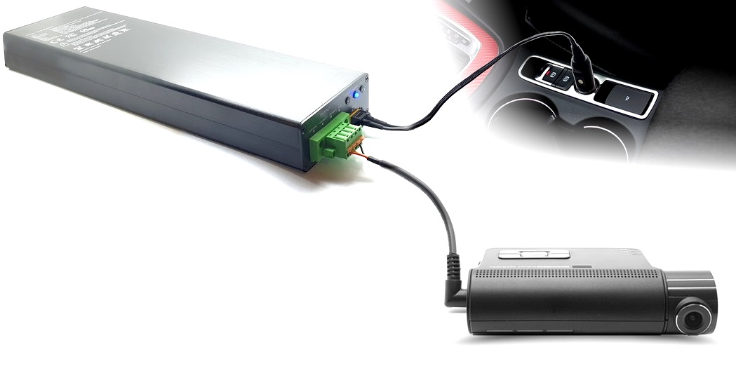
Connect the car cigar charger adapter to the INPUT terminal of the power bank. Connect the other end to the vehicle’s cigar lighter socket.
The power bank automatically begins charging when the vehicle ignition (ACC) is active. Ensure that the cigar socket provides power only when the ignition is ON.
Supported input range: 5V – 32V DC. Operating temperature range: -30°C to 70°C.
The device automatically disables charging if temperature limits are exceeded to protect internal battery cells and extend lifespan.
Maximum output current: 3A per port.
The device includes low-voltage cut-off protection to prevent deep discharge of the vehicle battery. However, it is recommended to use an ignition-based ACC power source whenever possible.
Connecting Your Dash Camera
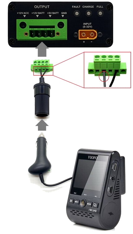
Use the dedicated green terminal plug to connect your dash camera. There are three supported connection methods:
Method 1 – Cigar Adapter (Simplest)
Connect the dash camera charger to the dedicated car cigar socket adaptor.
See diagram on page Dashcam Connection
Method 2 – Hardwire Connection
Requires a dedicated hardwire cable. Connect +12V ACC / +12V BATT / GND directly to the power bank terminal.
Always verify correct polarity.
See diagram on page Direct Dashcam Hardwire
Method 3 – Direct USB 5V Connection
For dash cameras with USB 5V mini or micro input only. USB cable must be correctly identified and wired.
Verify USB polarity before connection.
See diagram on page Direct 5V USB Connection
Direct Dashcam Hardwire
Method 2 – Hardwire Connection
- Please carefully follow the diagram to avoid damage to your camera.
- This method requires a dedicated hardwire accessory cable.
- Hardwire connection enables parking mode when the vehicle is parked.
- Installation should be performed by a qualified technician.
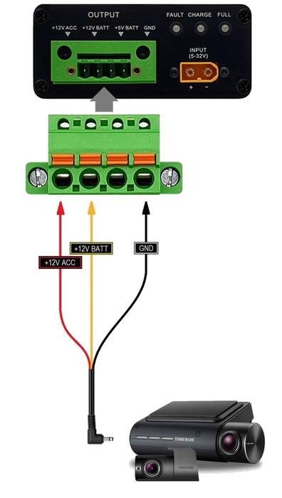
Verify cable colors using cable markings. Some dash camera manufacturers indicate +12V ACC as RED, others as YELLOW.
Green Cable Plug Terminal
How to Secure Cable in Plug Terminal
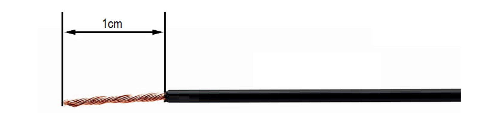
Prepare the Cable
- Strip the cable insulation to 1 cm.
Insert Cable into the Green Plug
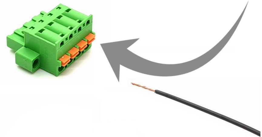
- Press and hold the orange locking button.
- Insert the stripped cable fully into the terminal hole.
- Ensure correct wire is inserted into the correct terminal.
- The plug contains 4 terminals, each assigned to different power lines.
- Maximum supported cable size: 12 AWG (3.31 mm²).
Verify the Connection
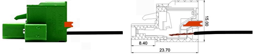
- The cable should be firmly secured inside the terminal.
- If the cable is loose, repeat Step 2.
- Ensure the conductor is inserted at least 1 cm deep.
External and Internal Construction
Hardwire Installation
Hardwire installation must be performed by a qualified car electrician only.
Power Connection
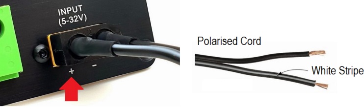
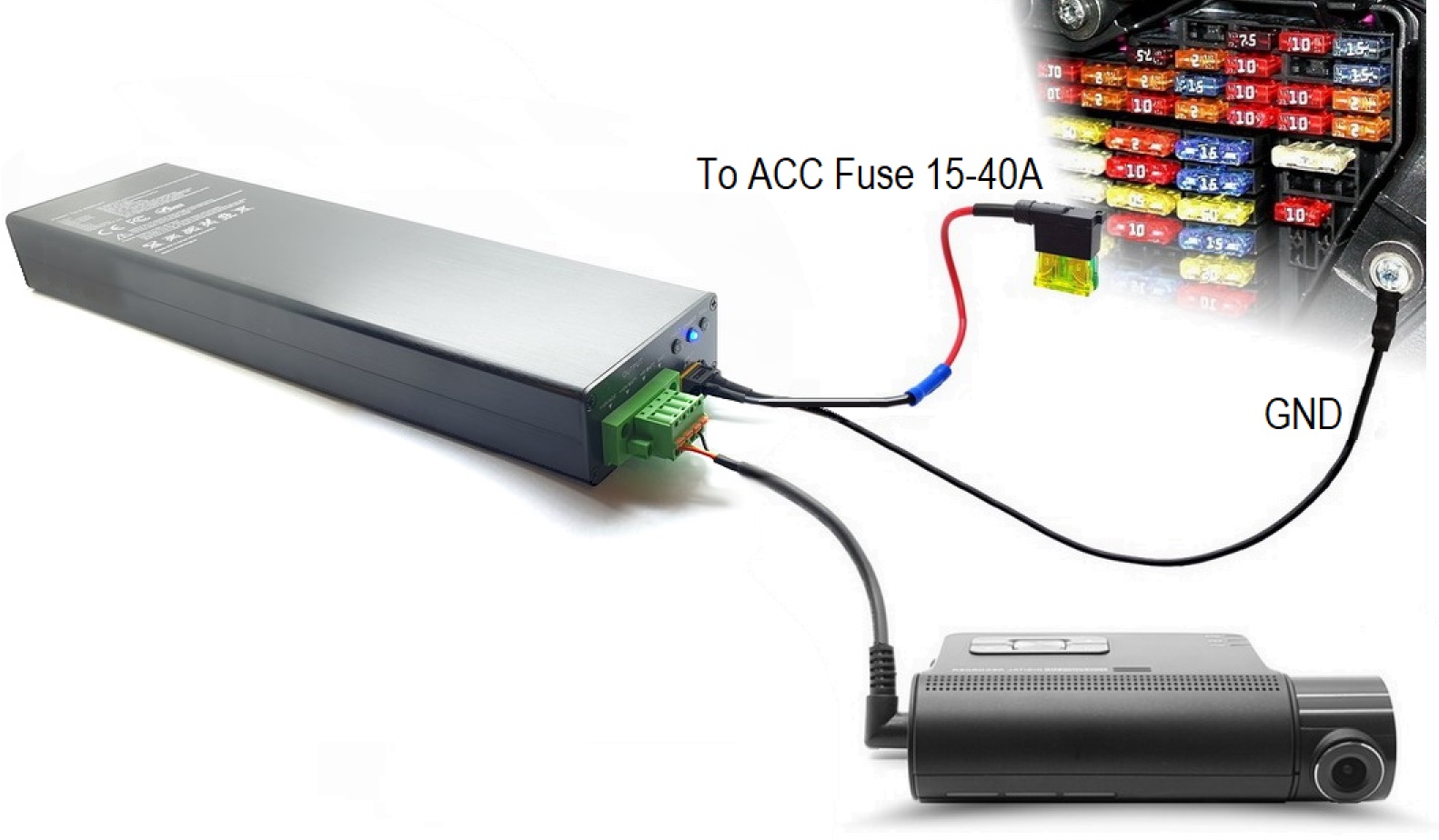
Connect the XT60 input connector to the vehicle fuse box. Identify and connect to ACC (ignition-switched power) and GND terminals.
Ensure correct positive (+) and negative (–) polarity. Refer to the markings on the power bank input connector.
Ignition-Based Power Only
Power must be supplied only when the ignition is engaged. Use ACC-switched fuse locations only.
Recommended Fuse Sources (15A or higher)
- Cigarette lighter fuse
- Car stereo fuse
- Power windows fuse
- Rear wiper fuse (rear only)
- Power seats fuse
- Heated seats fuse
- Heated steering wheel fuse
Ground Connection
Connect the ground wire to:
- GND terminal on the power bank, or
- Vehicle chassis ground point (near fuse box)
Ensure the metal surface is clean, rust-free, and not coated with paint.
Connection with a Dashcam
Connecting Your Dashcam to the Power Bank
There are three supported connection methods. Below is Method 1 – Standard (Simplest).
Direct Connection with 5V USB
Method 3 – USB Mini / Micro Dashcams Only
This method is intended only for dash cameras powered by stable 5V DC via USB Mini or Micro.
Connection Requirements
- Ensure the camera power supply provides stable 5V DC.
- Use high-quality cable (recommended AWG 13–24).
- Avoid converting PC USB data cables into power leads.
- Verify cable polarity using a multimeter before connection.
- Use continuity or diode test mode to confirm USB pin mapping.
- Identify positive (+5V) and negative (GND) wires according to USB pinout.
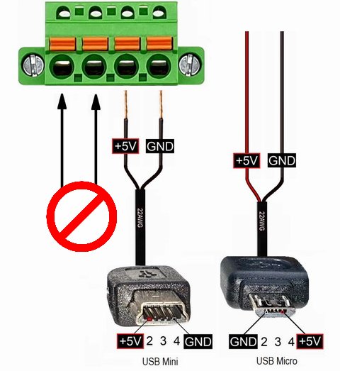
Incorrect USB polarity may permanently damage your dash camera. Cable colors do not always indicate polarity.
Although red is typically +5V, this is not guaranteed. Always confirm voltage and pinout using a multimeter.
Never connect USB dash cameras to +12V ACC or +12V BATT terminals. This will instantly damage the device.
Fault & LED Symptoms

Red LED Only
Very low input voltage (5V – 8V) or electrical fault detected.
Possible Causes
- Input voltage below 8V (must be above 12V).
- Input polarity reversed (hardwire method).
- Short circuit on output.
- Extended battery pack error.
Recommended Actions
- Verify correct polarity connection.
- Disconnect green output plug to check short circuit.
- Disconnect extended battery pack and restart charging.
- If issue persists, contact support@power-core.co.uk

Red + Blue LED
Charging current drop or temperature protection active.
Possible Causes
- Temperature too low (below 0°C).
- Temperature too high (above 60°C).
- Input voltage between 8V – 12.4V (charging disabled).
- Input voltage between 12.0V – 12.5V (reduced charging speed).
Action
- Check input voltage.
- Ensure operating temperature is within safe range.
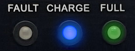
Green LED Blinking
Charging process reached approximately 60%.
The power bank is charging normally. Total charge time: approximately 60–80 minutes (model dependent).

Green LED Solid
Power bank is fully charged.
No errors detected. Device ready for operation.

Green LED Pulsing
Internal battery cell calibration in progress.
When Does This Happen?
- Power bank was fully discharged.
- Device was unused for extended period.
Calibration Process
- Leave device connected to power source.
- Calibration may take up to 5 hours.
- Green LED will remain solid when complete.
- Process continues automatically during regular use.
For best results, charge using a 12–28V power supply (5A or higher).
Extended Battery Connection
Power Core 6200LFP supports compatible external LiFePO4 extension battery modules via dedicated XT60 port.

Device Maintenance
Battery Care
- Use the power bank regularly.
- Avoid leaving the device fully discharged for more than 6 months.
- If stored unused, recharge to 100% before next use.
- If GREEN LED blinks slowly when fully charged, internal calibration is in progress.
- Leave connected up to 5 hours until LED remains solid.
Temperature & Environment
- Avoid temperatures above 60°C.
- Place in the coolest area of the vehicle (under seat or boot).
- Do not install in the engine bay.
- Avoid direct sunlight exposure.
- Protected against temperatures below 0°C.
- Avoid water and moisture.
Cable Safety
- Ensure cables do not interfere with Air-Bag systems.
- Secure all cables firmly.
- Avoid sharp edges.
- If installed under seat, ensure rails cannot cut wires.
Product Warranty Card

Thank you for choosing our product. The warranty period is valid for 24 months from the date of purchase.
Services Included at No Extra Cost
- Repair of quality-related defects during warranty period.
- Valid serial number required.
- Official seller stamp may be required.
Chargeable Services
- Invalid, missing, or damaged serial number.
- Incorrect or incomplete repair card information.
- Damage caused by improper installation or misuse.
- Water damage or mechanical damage.
- Force majeure events (fire, flood, lightning, etc.).
- Use contrary to provided instructions.