POWER CORE 22000LFP
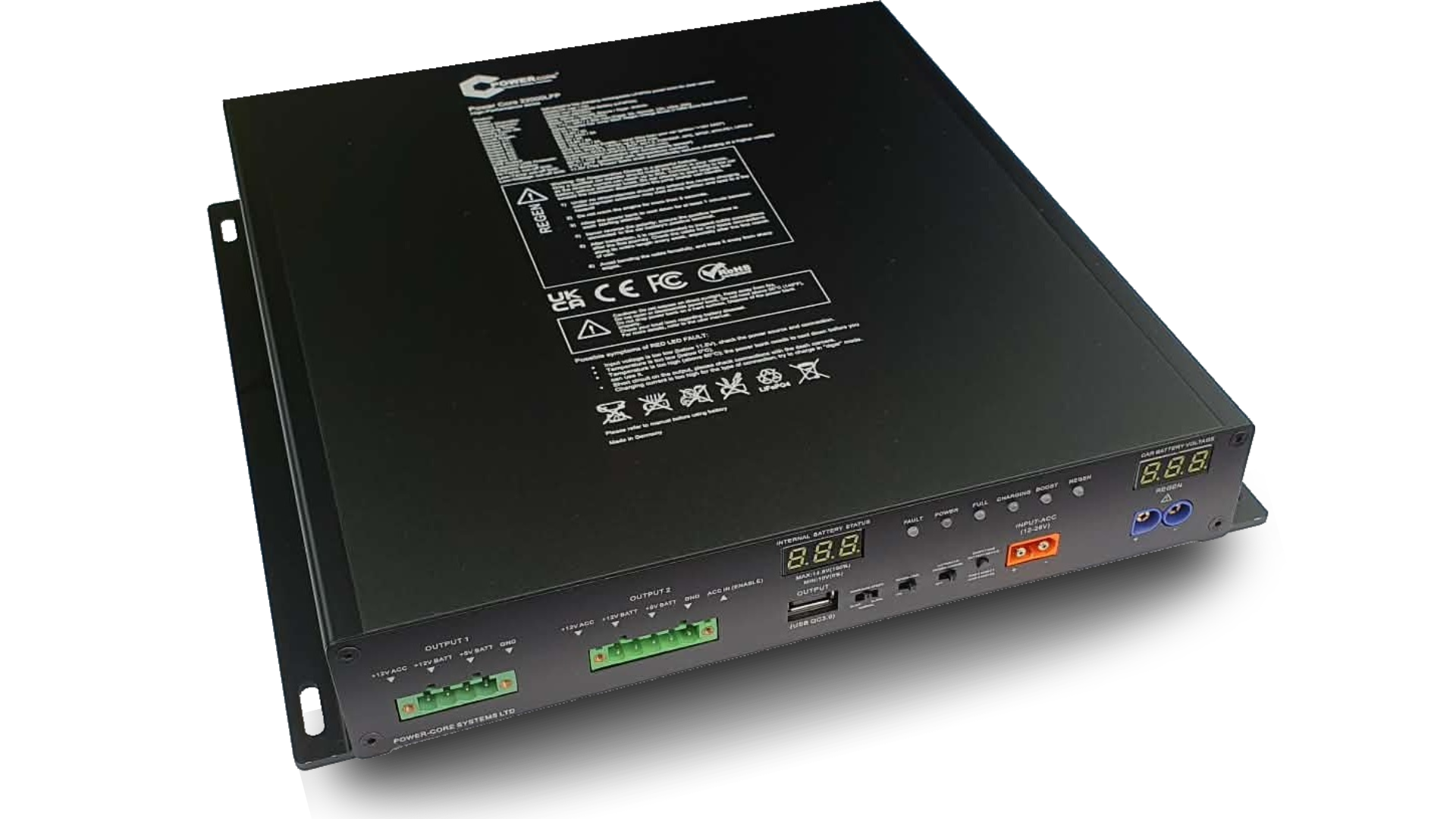
LiFePO4 Quick Charge Power Bank for Dash Camera

⚠ Safety Notice
Before using this device, carefully read the instruction manual included in the package. Improper installation or misuse may cause damage, fire hazard, or serious injury.
Critical Safety Warnings
- Do not expose the device to water, moisture, or fire.
- Do not use the device outside the operating temperature range (-30°C to 70°C).
- Do not strike, throw, drill, crush, or attempt to open the device.
- Do not disassemble or attempt to repair the battery.
- If smoke, unusual smell, or overheating is detected — immediately stop using the device.
Usage & Installation
- Keep away from children and do not allow use without adult supervision.
- Use only appropriate and compatible charging adapters.
- Avoid direct sunlight and keep away from heat sources.
- Ensure correct polarity during installation.
- Keep the device away from loose metal objects to prevent short circuits.
Battery & Storage
- Recharge fully at least once every 6 months if not in use.
- Allow full charge and discharge cycle every 6 months to maintain calibration.
- Store in a dry, ventilated environment.
- Extended inactivity may reduce battery performance.
♻ Disposal
- Dispose of the device at certified battery recycling stations only.
- Do not dispose of the battery in household waste.
Incorrect installation, reversed polarity, or physical damage may cause fire, electric shock, or permanent device failure.
Technical Specifications
General Information
Battery System
Total power-off mode (0mA)
Input and Output
+12V BATT @ 3A
+5V BATT @ 3A
GND
+12V BATT @ 3A
+5V BATT @ 3A
GND
ACC IN – charge activation pin (9V–28V), low current draw < 0.05A
Supported protocols: DCP, BC1.2, Apple, Samsung, Huawei FCP / SCP, AFC, SFCP, MTK PE1.1 / PE2.0
REGEN and Charging Performance
SLOW (5A): 4 h 30 min
NORMAL (12A): 1 h 50 min
ULTRA (15–20A): 1 h 20 min
SLOW (5A): 3 h 00 min
NORMAL (12A): 1 h 15 min
ULTRA (15–20A): 45 min
Simultaneous charging while engine is running
Temperature Range
Outputs remain active via automatic vehicle bypass
Outputs remain active via automatic vehicle bypass
Protection and Expansion
Low-temperature cut-off: 0°C
High-temperature cut-off: 60°C
Short-circuit protection
Reverse polarity protection
Soft start
Delay timer (15–30 sec selectable)
Over-discharge protection: 2.65V/cell (~10.6V)
Extended battery over-current protection
EMI-optimized design
Moisture-protected PCB coating
Features
Power Core 22000LFP
High-capacity LiFePO4 power bank for dash cameras with REGEN engine-start assist and high-speed charging.
Performance
- 22,000mAh / 281Wh high-capacity energy storage
- Designed for extended parking mode operation without draining the starter battery
- Charging current modes: 5A / 12A / 18A
- Up to 250W charging performance
- 15 minutes of charging can provide up to 24 hours of recording (1-channel dashcam)
- Suitable for long-duration parking protection and higher-demand camera systems
Battery Technology
- LiFePO4 chemistry for improved thermal stability and long cycle life
- Over 5,000+ charge cycles
- 4S2P internal cylindrical cell configuration
- Active cell balancing for stable long-term performance
- Predictable voltage behavior for automotive use
- Expandable with optional external battery modules
REGEN Technology
- REGEN engine-start assist with up to 100A peak
- Helps reduce voltage sag during engine start
- Supports weak or aging vehicle batteries
- Improves stability of sensitive vehicle electronics during cranking
- Reverse polarity protected
- Real-time visual LED indication of assist activity
Charging & Power Delivery
- Pass-through operation: charge and power loads simultaneously
- Dashcam remains powered while the power bank is charging
- Dual dash cam outputs supporting two independent camera systems
- Low-voltage input protection suspends charging below 12V
- 30-second soft-start charging delay reduces electrical stress
- High efficiency with low heat generation
- USB QC3.0 output for compatible auxiliary devices
Protection & Safety
- Multi-layer protection system
- Reverse polarity protection
- Short-circuit protection
- Temperature cutoff logic
- Fuse-based overcurrent protection
- Controlled low-voltage behavior for automotive environments
Installation & Design
- Full aluminum enclosure for improved heat dissipation and durability
- Laser-engraved housing markings
- Push-button terminal connector for fast, tool-free wiring
- No screw terminal tightening required for camera connection
- Cleaner and faster installation than traditional terminal blocks
- Supports +12V ACC signal for dashcam parking mode control
Power Bank Diagram
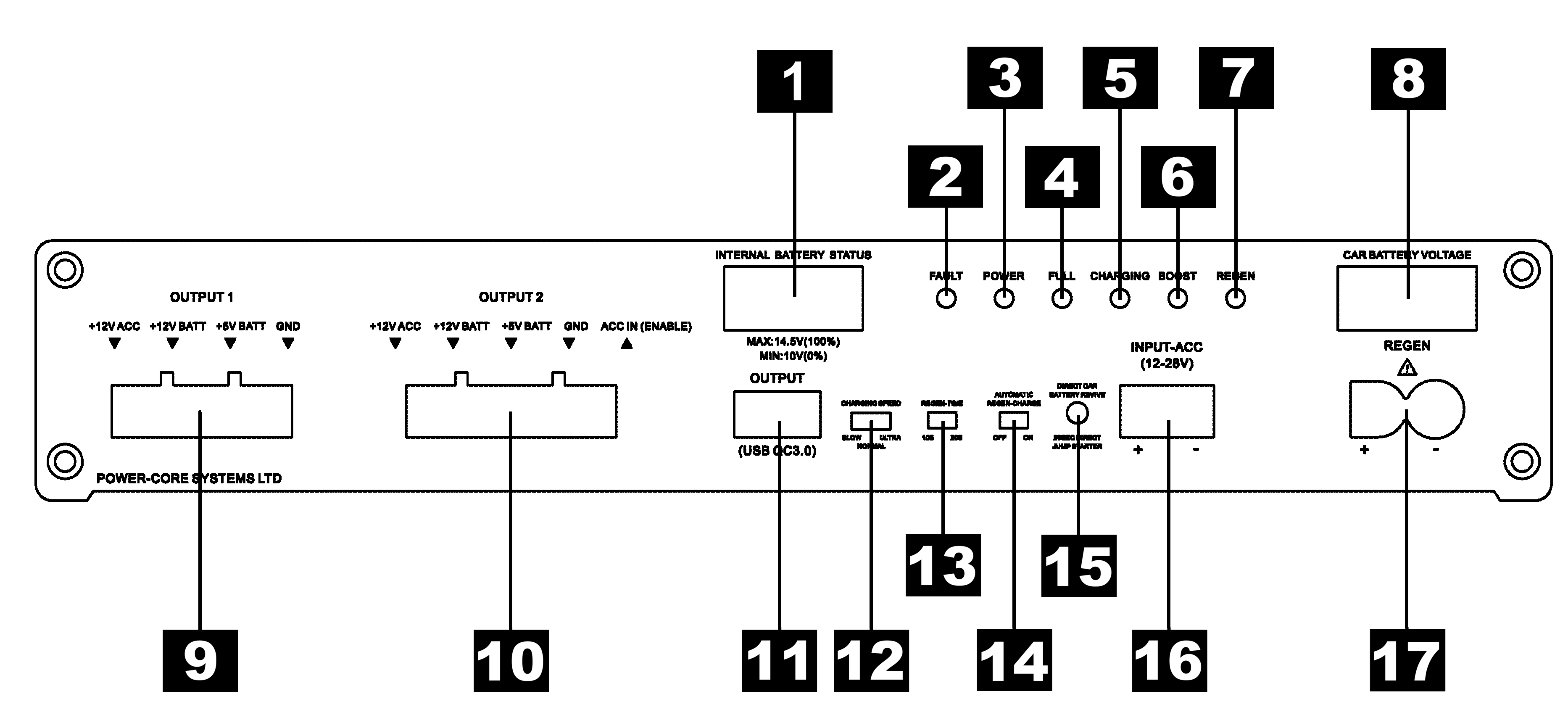
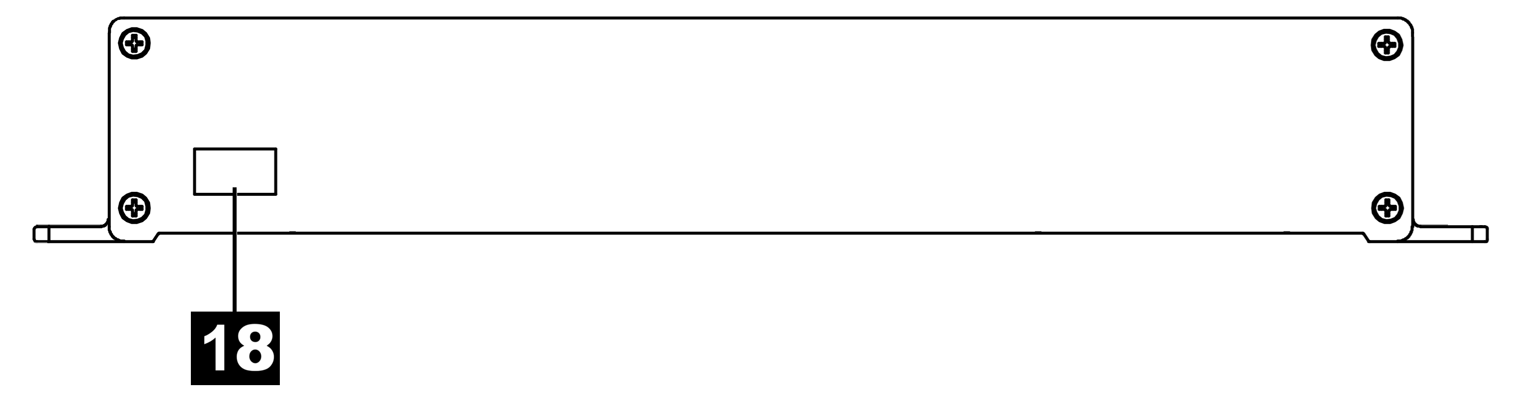
Diagram Legend
Installation Guidelines
Hardwire installation must be performed by a qualified car electrician only.
This section explains the recommended hardwire installation method for the Power Core 22000LFP. The Charge Enable PIN5 connection is optional. During installation, connect the GND wire to a clean chassis surface or other suitable ground point.
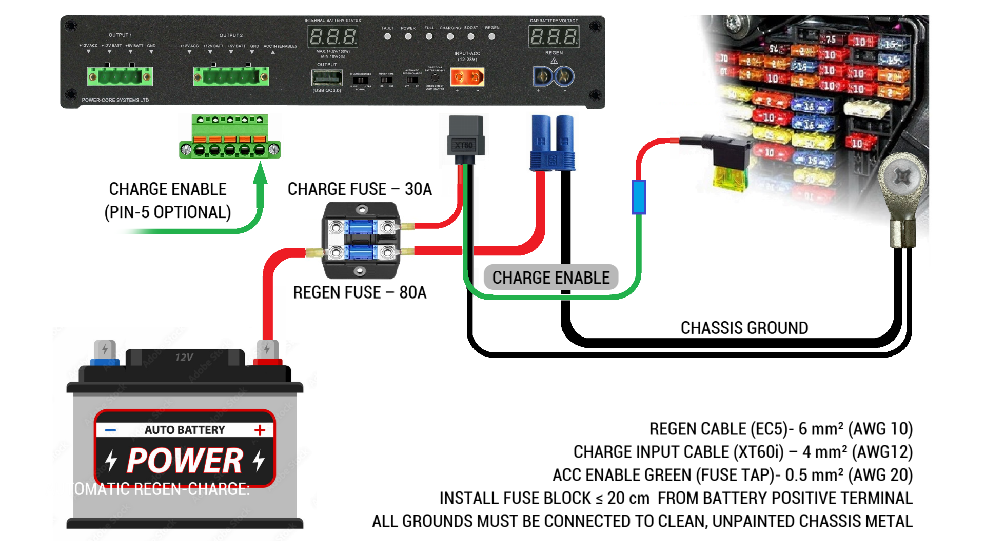
Complete installation overview with fuse block, ACC fuse tap, charging input and REGEN wiring.
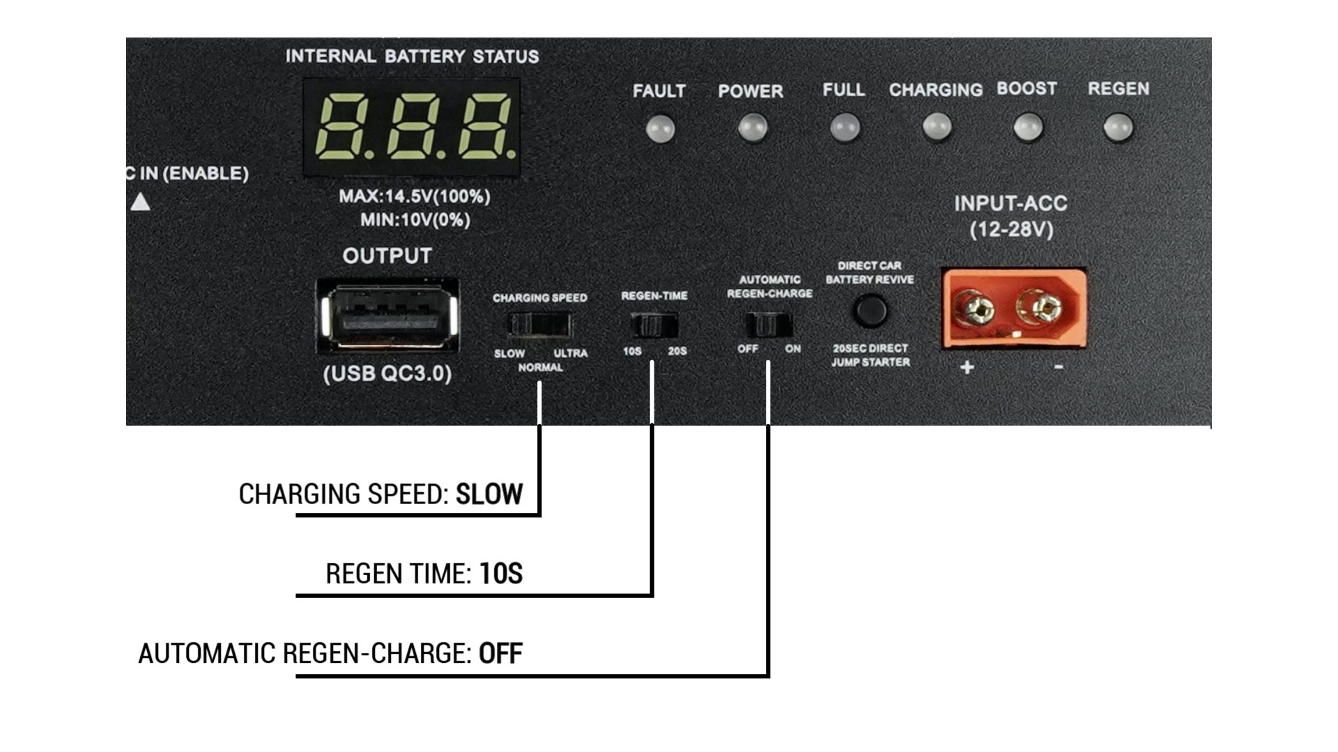
Recommended initial switch settings before any wiring is connected.
Before Any Wiring
Initial Device Settings
- Set CHARGE SPEED to LOW.
- Set REGEN to OFF.
- Set REGEN TIME to 10 seconds.
- Disconnect the vehicle battery, starting with the negative terminal first.
Select a Safe Installation Area
- Install the unit under a seat or inside the trunk.
- Do not install the unit inside the engine bay.
- Avoid high-temperature or high-moisture areas.
- Do not connect any cables at this stage.
Charge Enable Wire and ACC Fuse Source
The green Charge Enable wire must be connected to an ignition-switched, low-priority fuse that receives ACC power only when the engine is running or the ignition is ON. The Charge Enable PIN5 connection is optional, but recommended for correct ignition-based charging control.
Recommended Fuse Sources (3A or Higher)
- Cigarette lighter fuse
- Car stereo fuse
- Power windows fuse
- Rear wiper fuse (rear only)
- Power seats fuse
- Heated seats fuse
- Heated steering wheel fuse
Ground Connection
Permitted Ground Points
- GND terminal on the power bank, or
- Vehicle chassis ground point near the fuse box.
Grounding Requirements
- The metal surface must be clean, rust-free and unpainted.
- Connect the XT60i BLACK ground cable to clean chassis metal.
- If REGEN will be used, connect the BLACK REGEN GND cable as well.
- Never connect any RED wire before the ground connection is completed.
Step-by-Step Installation
Connect Ground (GND)
- Connect the XT60i BLACK ground cable to clean chassis metal.
- If REGEN will be used, connect the BLACK REGEN GND cable.
- The surface must be unpainted and corrosion-free.
- Never connect the RED wire before ground.
Connect Fuse Block
- Connect the RED charging wire to the 30A CHARGE fuse.
- Connect the RED REGEN wire to the 60A REGEN fuse.
- Install the fuse block within 20 cm or less from the battery positive terminal.
- Do not connect the fuse block to the battery yet.
Connect to Battery
- Connect the fuse block to the battery positive terminal (+).
- Verify polarity: RED = + / BLACK = GND.
- Reconnect the original vehicle battery terminals.
- No LEDs should be ON at this stage. This is normal.
Connect the GREEN ACC Wire
- Select an ignition-switched low-priority fuse.
- Recommended fuse sources include seat heating or rear window heater circuits.
- Do not use airbag, ABS or ECU fuses.
- Use a fuse tap (piggyback type).
- Keep the engine OFF during connection.
- Select a fuse rated at 5A or higher.
Recommended ACC Fuse List
- Rear window defroster
- Seat heater fuse
- Heated steering wheel fuse
- Heated front windshield
Test Ignition Logic
Expected LED Behavior
- Ignition OFF → no LEDs
- Ignition ON → POWER LED and voltage display active
- After 10 seconds → CHARGING LED
- Ignition OFF → all LEDs OFF
If Charging Continues with Ignition OFF
The selected fuse provides constant power. Move the fuse tap to another ignition-switched fuse that cuts power when the ignition is OFF.
First Charging and Installation Verification
- After first installation, use SLOW or NORMAL charging mode only.
- Do not use ULTRA mode during initial testing.
- After the first journey, re-check all connections, especially the GND ring terminal.
- Secure all wires to prevent movement caused by vibration.
- Route cables away from sharp edges and seat rails.
- After charging, touch the fuse block and charging terminals to verify temperature. They should not be hot.
Built-in Protection Systems
After Extended Use
Re-check the fuse block and GND connection after longer trips. If no issues are detected, ULTRA charging mode may then be enabled.
Operational Limitations
- The REGEN feature is designed only for petrol or diesel vehicles.
- Do not use with hybrid or electric vehicles.
- Vehicle operating voltage must remain within the 12V – 14.6V range.
- Designed for standard 12V AGM lead-acid battery systems.
- The fuse becomes hot to the touch.
- A burning smell appears.
- Visible cable damage is detected.
Disconnect the power cable from the power bank immediately and inspect the installation. Most electrical faults are caused by poor crimping, loose grounding, incorrect fuse placement, or short circuits before the power bank.
Charging Modes
The Power Core 22000LFP offers three selectable charging modes: Slow, Normal, and Ultra. Each mode changes the charging current, charging time, and load placed on the vehicle electrical system. Selecting the correct mode improves charging performance, installation safety, and long-term reliability.
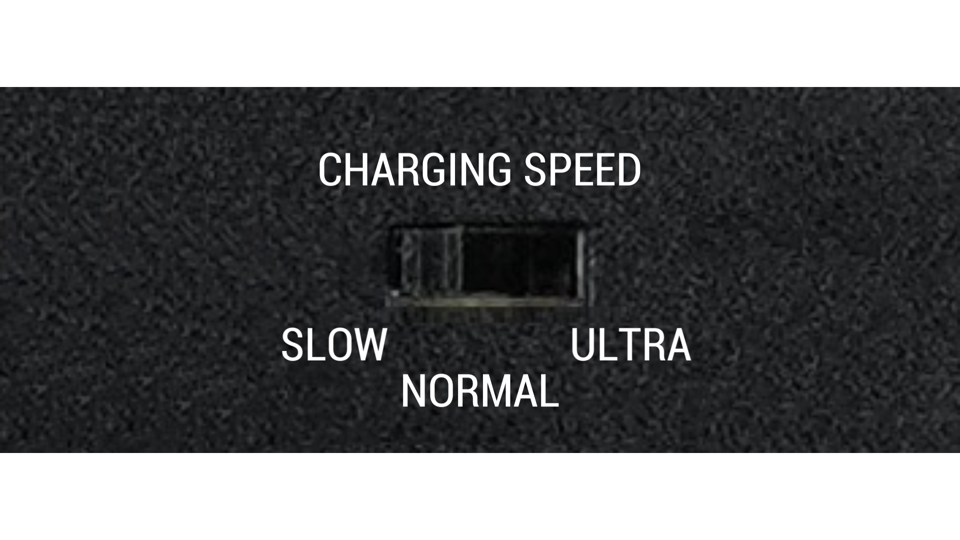
Charging speed selector with SLOW, NORMAL and ULTRA charging modes.
| Mode | Charging Current | Approx. Charging Time | Recommended Use | System Load |
|---|---|---|---|---|
| Slow | 5A | Approx. 4 h 30 min | Home charging, wall charger, lower-power 12V/24V supplies, optional cigarette lighter charger | Lowest load / maximum safety margin |
| Normal | 12A | Approx. 1 h 50 min | Standard daily use, hardwire vehicle installation, most recommended operating mode | Moderate load / balanced performance |
| Ultra | 18–20A | Approx. 1 h 20 min | Short journeys where maximum recharge speed is required | High load / requires high-quality installation |
When ULTRA mode is enabled, the BOOST LED is illuminated.
Lowest Load / Highest Safety Margin
- Recommended when using a standard wall charger or other limited-power supply.
- Suitable for optional charging from a vehicle cigarette lighter accessory.
- Recommended for safe home charging.
- The power bank automatically adapts to input voltage in the 12V–24V range.
- Any stable power supply rated around 80W or higher should be sufficient for this mode.
Standard Recommended Mode
- This is the standard and recommended charging mode for regular vehicle use.
- Provides fast charging while keeping alternator load at a level most vehicles can handle safely.
- Offers a good balance between charging speed and installation reliability.
- Compared with ULTRA mode, it places less thermal and mechanical stress on connectors and wiring.
- Recommended when long-term durability and battery system lifespan are a priority.
Maximum Charging Speed
- Designed for short journeys where the fastest possible recharge is required.
- Places a significantly higher current load on wiring, fuse connections and crimp terminals.
- Should only be used with a correctly installed hardwire system in very good condition.
- All power and ground connections must be tight, clean and checked periodically.
- Professional installation is strongly recommended before using ULTRA mode.
Which Mode Should I Use?
Use Slow mode when charging from a standard wall adapter, a lower-power source, or when maximum safety margin is preferred.
Use Normal mode for everyday operation in most vehicles. This is the best all-round setting for charging performance, alternator load and long-term reliability.
Use Ultra mode only when rapid charging is necessary and the installation has been professionally completed and inspected.
- ULTRA mode can draw up to 20A during charging.
- High current increases the importance of correct crimping, fuse placement, cable routing and ground quality.
- Loose terminals or poor grounding can create resistance, which leads to voltage loss and heat build-up.
- Vehicle vibration over time may loosen poorly secured connections.
- Inspect all high-current wiring regularly, especially fuse holders, ring terminals, XT60i connections and chassis ground points.
- If any connector, fuse holder or cable becomes warm or hot during charging, stop using ULTRA mode immediately and inspect the installation.
- Do not use ULTRA mode as the first test mode after installation. Start with SLOW or NORMAL and verify stable operation first.
REGEN Function – Reverse Battery Boost
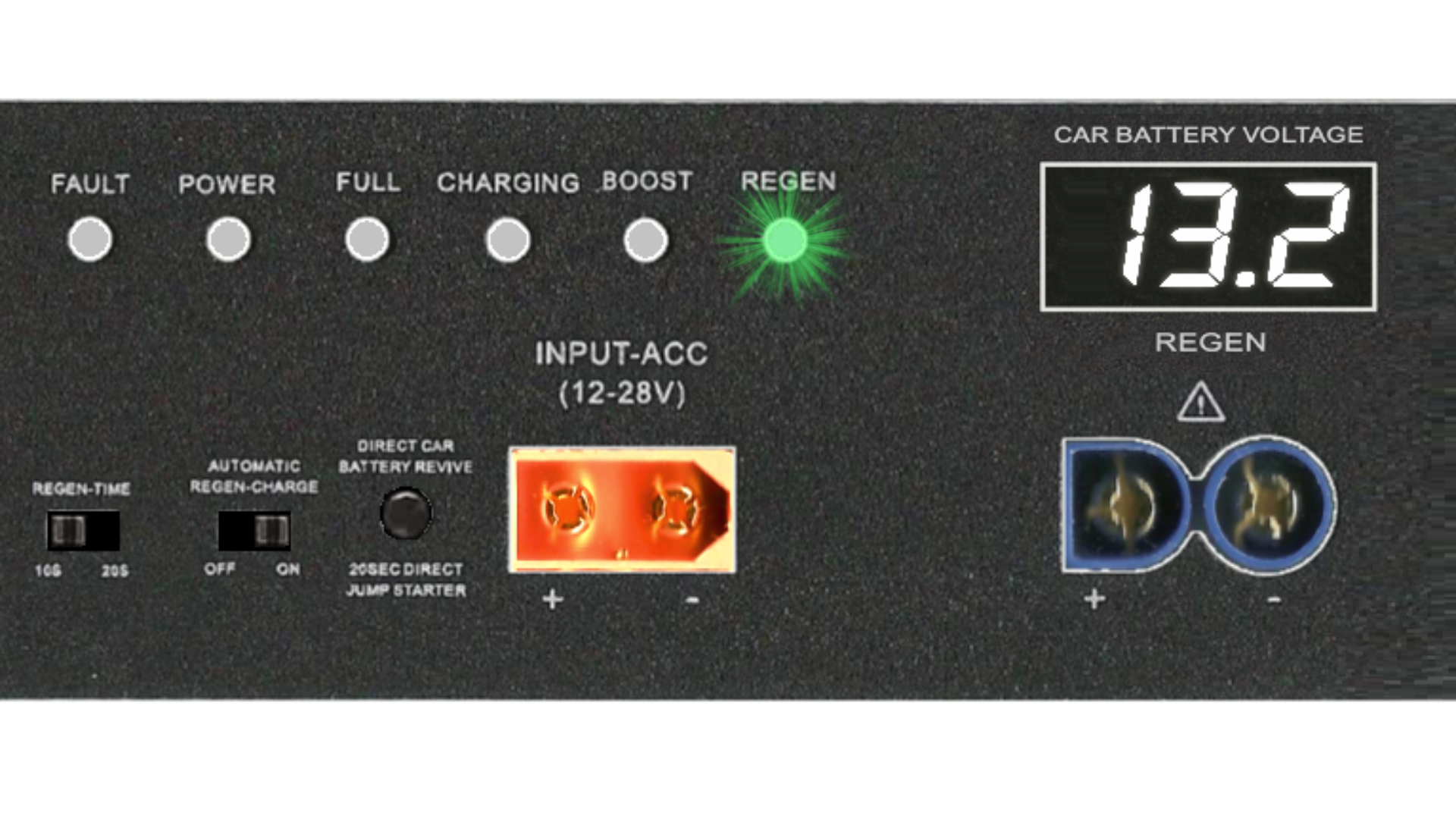
REGEN LED indicator and car battery voltage monitor during reverse boost operation.
What is the REGEN Function?
The REGEN (Reverse Charge Boost) feature assists the vehicle battery during engine starting. When the function is enabled, the power bank can temporarily deliver high current support to the car battery during the engine cranking process.
The system monitors the vehicle ACC signal provided through the green ACC wire. When the ignition is turned to the engine start position, the power bank automatically detects the cranking event and briefly supplies additional current to support the vehicle battery.
This can improve engine start reliability in situations where the vehicle battery voltage drops during starter motor operation.
Battery Capacity Allocation
Internal Energy Management
- Total internal capacity: 22000 mAh
- When REGEN is ON, approximately 7000 mAh is reserved for engine start support.
- In this mode, approximately 15000 mAh remains available for powering external devices such as a dash camera.
- When REGEN is OFF, the full internal capacity of the power bank can be used for connected output devices.
- The REGEN reserve is automatically recharged during normal charging operation.
Reverse Boost Operation
- REGEN is active only when the REGEN switch is set to ON.
- The duration of reverse boost is controlled by the REGEN TIME switch.
- The recommended setting for most installations is 10 seconds.
- After the preset support time expires, the system automatically returns to standard charging mode.
LED Indicators
Green REGEN LED
- Indicates REGEN function is enabled.
- Shows that the system is correctly connected to the vehicle battery.
- Continuous green light means the system is ready to provide engine start boost.
Red REGEN LED
- Red illumination indicates high reverse current flow.
- This usually occurs when the starter motor is cranking the engine.
- The brightness increases with current load.
During the boost process the Car Battery Voltage Monitor is also active, displaying the real-time voltage supplied to the vehicle battery. A temporary voltage drop during engine cranking is normal.
After the preset delay time expires, the system automatically switches from reverse boost mode to standard charging mode. A small internal relay click may be heard during this transition — this is normal.
Protection System
- Reverse polarity protection is built into the REGEN circuit.
- If polarity is connected incorrectly, the RED FAULT LED will flash and an audible alarm will sound.
- This protection prevents damage to both the power bank and the vehicle battery.
- The REGEN circuit uses a dedicated internal battery cell section for high current output.
- An internal self-resetting fuse protects the REGEN output.
Internal protection fuse specification:
- Trip current: approx. 80A
- Maximum peak current: 100A
- 50A sustained: up to approx. 5 seconds
- 80A sustained: up to approx. 2 seconds
- 100A peak: ≤ 1 second
- The REGEN circuit can deliver reverse current up to approximately 80A.
- Always install the REGEN cable directly to the vehicle battery using a 60–80A fuse.
- Professional installation by a qualified automotive electrician is strongly recommended.
- Never extend the REGEN cable — extension may overheat or melt during engine starting.
- Do not crank the engine longer than 3 seconds per attempt.
- Allow at least 1 minute cooling time between start attempts.
- Never reverse battery polarity.
- Avoid sharp cable bends and protect the cable from sharp edges.
- Inspect the cable and all connections regularly, especially during the first month of use.
The REGEN cable should be installed as short as possible and secured near the vehicle battery. Incorrect installation may result in overheating, electrical faults, or damage to the vehicle electrical system.
The manufacturer is not responsible for damage resulting from improper installation.
Direct Car Battery Revive – Manual Jump Start Support
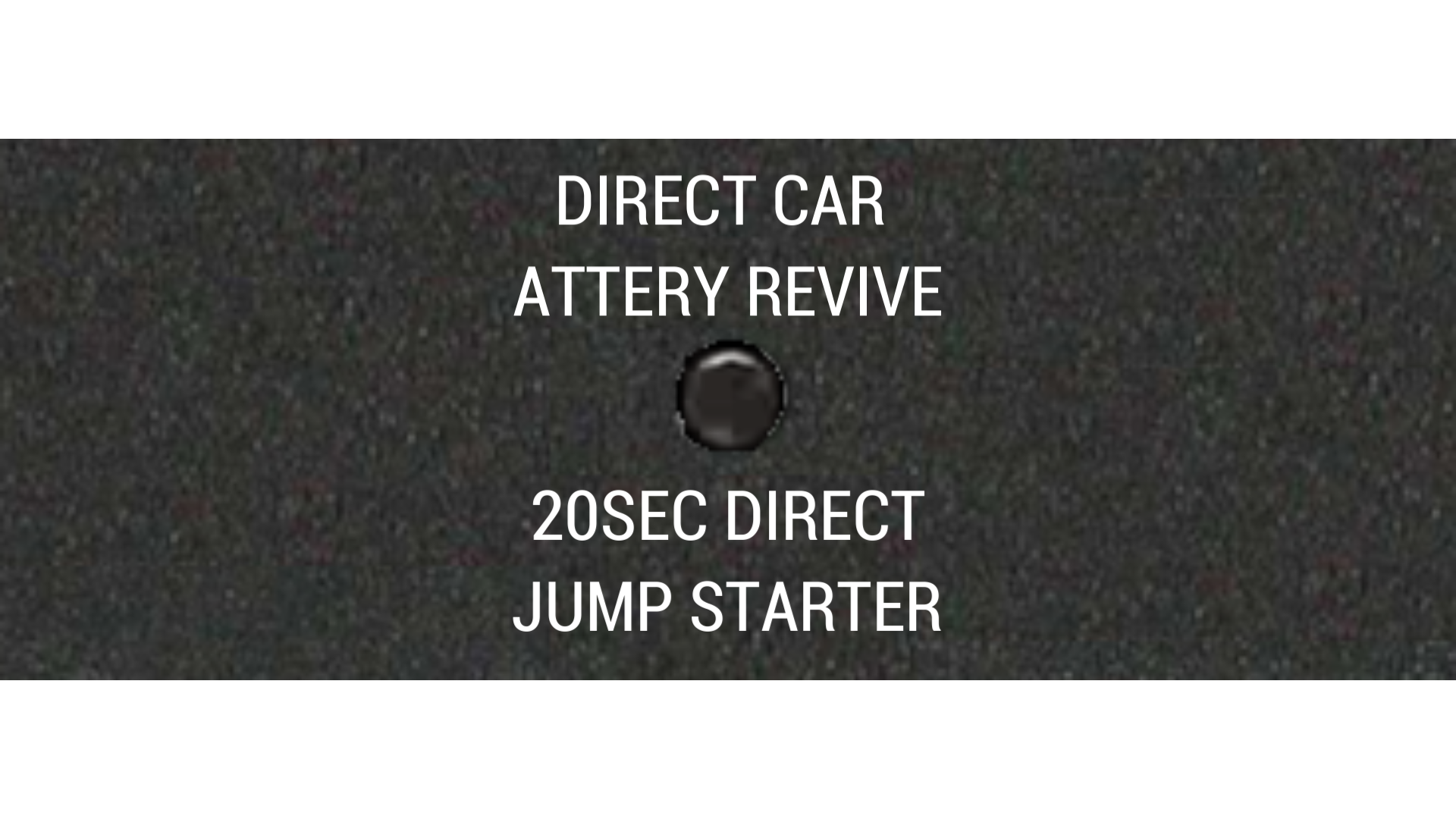
Manual button used to activate temporary support power on the REGEN output.
The Direct Car Battery Revive button manually forces the power bank to supply power to the REGEN output. This function is intended as a temporary engine start support feature for a weak vehicle battery.
The function is activated by pressing the button once briefly. After activation, the power bank automatically supplies support power to the REGEN output for approximately 30 seconds, then switches off automatically.
This feature is designed to support a connected vehicle battery, not to replace it. It helps stabilize battery voltage before cranking and provides additional current support during engine start.
This function may also be used to assist another vehicle when necessary, provided that the connection is made correctly and polarity is verified before activation.
How It Works
Manual Activation
- Press the button once briefly to activate the function.
- The power bank automatically enables output power on the REGEN terminal.
- The support cycle remains active for approximately 30 seconds.
- After 30 seconds, the function switches off automatically.
Important Functional Limitation
- Do not treat this function as a substitute for a missing or disconnected vehicle battery.
- The system is intended to operate with a vehicle battery connected.
- Its purpose is to supplement battery voltage and current during engine start.
- Best results are achieved when the vehicle battery is weak, but still installed and properly connected.
Recommended Use
Connection Procedure
- First, connect the cables directly to the vehicle battery that requires starting support.
- For this temporary support procedure, connect directly to the battery terminals without any additional external fuse in the cable path.
- Then connect the REGEN connector to the prepared cables.
- Press the Direct Car Battery Revive button once briefly.
- You then have approximately 30 seconds to start the engine.
Starting Procedure
- After activation, crank the engine within the 30-second active window.
- Do not crank the engine for more than 3 seconds per attempt.
- If the engine does not start, wait at least 1 minute before trying again.
- Always verify correct polarity before connecting the REGEN output.
- This function can deliver very high current to the REGEN output.
- Use only with suitable high-current cables and secure battery connections.
- Do not use this function to start engines that exceed the supported engine size or starting load of the system.
- Do not crank the engine for more than 3 seconds per attempt.
- Allow at least 1 minute cooling time between attempts.
- Never reverse polarity. Positive must always be connected to battery positive.
- Never allow the connected cables or terminals to touch each other or any grounded metal parts.
- Do not bend the cable sharply and keep it away from sharp edges, moving parts and heat sources.
- Inspect all cable connections regularly, especially during the first month of use.
Protection System
The Direct Car Battery Revive output is protected in the same way as the REGEN circuit. An internal self-resetting protection fuse limits output in case of overload, excessive current draw or short circuit conditions.
- Internal fuse type: self-resetting protection fuse
- Trip current: approx. 80A
- Maximum peak current: 100A
- 50A sustained: up to approx. 5 seconds
- 80A sustained: up to approx. 2 seconds
- 100A peak: ≤ 1 second
LED Indicators Explanation
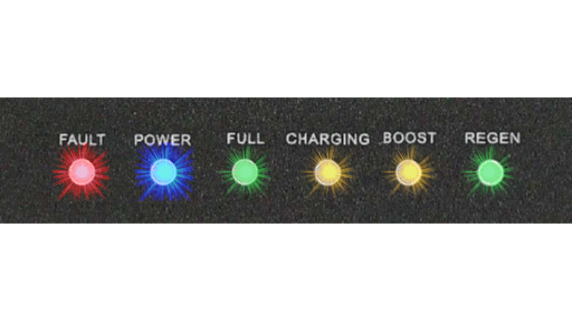
Main status LEDs used to indicate power, charging state, fault conditions and REGEN operation.
The Power Core 22000LFP uses dedicated LED indicators to show operating status, charging state and fault conditions. The table below explains the meaning of each LED and when it should normally be visible.
| LED | Color | Meaning | Typical Behavior |
|---|---|---|---|
| FAULT | Red | Indicates an important fault condition. | This LED may turn on when a serious wiring or operating fault is detected, especially if REGEN polarity is connected incorrectly. In this case, an audible alarm will also sound. |
| POWER | Blue | Indicates that ignition-switched input power has been detected. | Under normal installation, this LED should be on only when the vehicle ignition is ON. |
| FULL | Green | Indicates that the internal battery is fully charged. | The FULL LED typically turns on when the power bank reaches approximately 98–100% charge. |
| CHARGING | Amber | Indicates that the charging process is active. | This LED turns on after the preset delay time, provided that all charging conditions are met: internal temperature within operating range, input voltage above 12V, no fault detected, and correct power connection. It turns off when charging stops or when the battery becomes full. |
| BOOST | Amber | Indicates ULTRA fast charging mode. | This LED shows that high-current charging is enabled. It may turn off if the available input power is insufficient, if ULTRA charging conditions are not met, or when the battery is nearly full. Slight changes in LED brightness are normal. |
| REGEN | Green / Red | Indicates REGEN status and reverse current activity. | A constant green REGEN LED indicates correct REGEN connection and readiness to support engine start. A red REGEN indication appears during engine cranking and shows reverse current flow. Higher load may result in brighter red illumination. |
Charging Conditions for the CHARGING LED
CHARGING LED Turns On When
- The preset delay time has elapsed.
- The internal temperature is within the operating range of approximately 1°C to 49°C.
- The input voltage is above 12V.
- No fault condition is detected.
- The input power source is connected correctly and can provide sufficient power.
BOOST LED Behavior
- The BOOST LED is associated with ULTRA charging mode.
- It indicates that the unit is attempting high-current charging.
- If the power source cannot provide enough current, the LED may turn off.
- Brightness variation may occur during operation and is considered normal.
REGEN LED Behavior
Green REGEN
- REGEN is switched ON.
- REGEN wiring is connected correctly.
- The system is ready to assist engine start.
- This is the expected LED state during parking mode when REGEN support is enabled.
Red REGEN
- Indicates reverse current flow to the vehicle battery.
- Usually appears during engine cranking.
- Higher current draw may produce a brighter red indication.
- When REGEN is ON, only the REGEN LED should remain visible while the vehicle is parked and the ignition is OFF.
- If any other LED remains on with the ignition OFF, the ACC / green charge enable wire is most likely connected to the wrong fuse.
- In this case, move the ACC fuse connection to a true ignition-switched fuse that loses power when the engine is OFF.
- Typical recommended fuse sources include seat heater or rear window heater circuits.
Battery Voltage Monitor
The Internal Battery Voltage Monitor displays the real-time voltage of the internal battery pack. This is a numeric segment LED display showing the voltage of the built-in 4S LiFePO₄ battery system.
The internal control circuit manages both charging and discharging within an operating range of approximately 10V to 14.6V. During charging, the displayed voltage gradually rises as the battery approaches full charge.
The display is intended as a live voltage reference, not as a precise percentage meter. Because LiFePO₄ batteries maintain a very stable voltage for much of the charging cycle, voltage does not increase linearly with battery percentage.
How the Display Works
4S LiFePO₄ Segment Display
The monitor shows the total pack voltage of four LiFePO₄ cells connected in series (4S configuration).
- Maximum charging voltage: 14.6V
- Nominal battery voltage: approx. 13.2V
- Minimum protected voltage: approx. 10V
- The display becomes active during charging.
- Voltage rises from approximately 10V to 14.6V throughout the charge cycle.
Important Characteristics
- LiFePO₄ voltage remains relatively stable through most of the charge range.
- A battery reading around 13.0V–13.3V may still represent a wide state-of-charge range.
- The final rise toward 14.6V occurs mainly during the absorption phase.
- This behavior is normal and typical for LiFePO₄ battery chemistry.
Approximate Voltage vs Battery Level
| Battery Level | Voltage | Typical Condition |
|---|---|---|
| 100% | 14.6V | End of charge / absorption complete |
| 95% | 13.6V | Very high state of charge |
| 90% | 13.4V | Near full |
| 80% | 13.3V | High charge level |
| 70% | 13.2V | Nominal LiFePO₄ range |
| 60% | 13.1V | Normal operating level |
| 50% | 13.0V | Mid charge range |
| 40% | 13.0V | Mid-to-lower charge plateau |
| 30% | 12.9V | Lower operating range |
| 20% | 12.8V | Low battery level |
| 10% | 12.0V | Very low battery level |
| 0% | 10.0V | Minimum protected discharge level |
LiFePO₄ Charging Curve
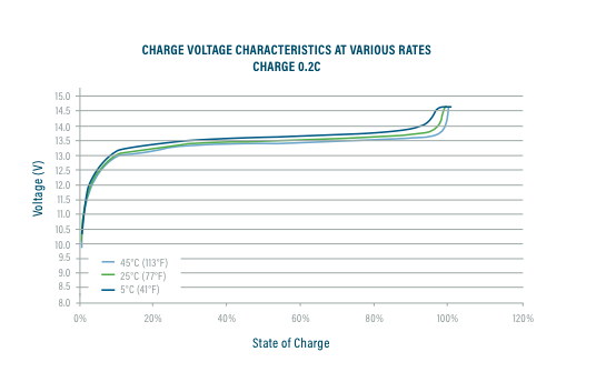
Typical LiFePO₄ voltage response during charging. Most of the charge cycle occurs in a relatively narrow voltage range, followed by a final rise during the absorption stage.
Why Voltage Changes Slowly
LiFePO₄ batteries do not behave like lead-acid batteries. Voltage increases quickly at the beginning, then remains quite stable for most of the charging process.
- Rapid initial rise from about 10V to around 13V
- Long plateau through most of the usable capacity range
- Final rise to 14.6V near full charge
How to Read the Display Correctly
- Use the display as a live voltage indicator.
- Do not interpret small voltage changes as exact percentage changes.
- A reading near 13.2V is typical for a healthy LiFePO₄ pack.
- The display is most useful for observing charging progress and verifying normal battery behavior.
- The voltage display shows real pack voltage, not a fixed state-of-charge percentage.
- Voltage will naturally change during charging and may also vary with temperature and load.
- A stable reading during part of the charge cycle is normal for LiFePO₄ batteries.
- The final rise toward 14.6V does not occur evenly across the entire charging process.
How to Use the Device
Proper installation is required before using the device. Follow the instructions provided in Installation Guidelines. Incorrect installation or missing connections will prevent the power bank from operating correctly.
The power bank requires correct input wiring and at least one properly connected output device (dash camera or load) to function as intended.
The device is equipped with two independent output terminals, allowing connection of up to two separate dash camera systems. Both outputs support parking mode operation.
Typical Operation
Driving (Charging Mode)
- The device charges automatically when the engine is running.
- Charging speed depends on selected mode (Slow / Normal / Ultra).
- Dash cameras remain powered during charging (pass-through mode).
Parking Mode
- The power bank supplies power to the dash camera when the engine is OFF.
- Parking mode operation depends on dashcam wiring method.
- Battery protects the vehicle starter battery from discharge.
REGEN / Support Mode
- REGEN can support vehicle battery during engine start.
- Provides additional current during cranking.
- Used only when properly installed and configured.
Dash Camera Connection Methods
Dash cameras can be connected using several methods depending on the camera model and desired functionality.
1. Cigar Charger Connection (Simple)
- Uses standard car cigarette socket adapter.
- Quick and easiest installation method.
- Parking mode may not be supported (depends on camera).
2. Hardwire Connection (Recommended)
- Uses dedicated hardwire cable (2-wire or 3-wire).
- Provides full parking mode functionality.
- Most stable and professional installation method.
3. Direct 5V Connection (Advanced)
- Direct connection to 5V output.
- Requires compatible camera and correct wiring.
- Parking mode may not be supported.
4. USB Output (QC3.0)
- Supports fast charging for USB devices.
- Can power dashcams, mobile devices or WiFi routers.
- Useful for cloud-connected dash camera setups.
Green Cable Plug Terminal
How to Secure Cable in Plug Terminal
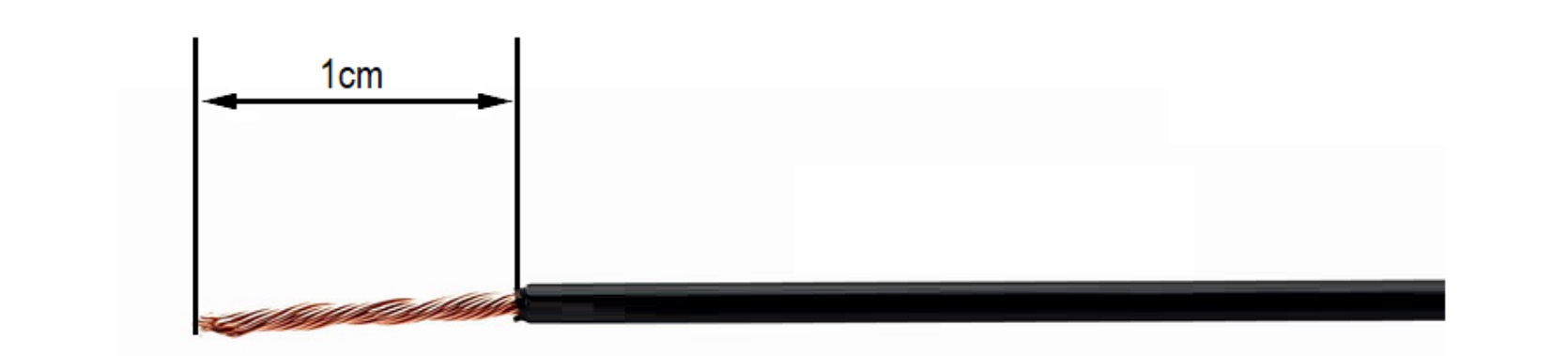
Prepare the Cable
- Strip the cable insulation to 1 cm.
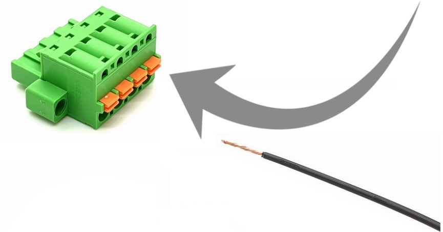
Insert Cable into the Green Plug
- Press and hold the orange locking button.
- Insert the stripped cable fully into the terminal hole.
- Ensure correct wire is inserted into the correct terminal.
- The plug contains 4 terminals, each assigned to different power lines.
- Maximum supported cable size: 12 AWG (3.31 mm²).
Verify the Connection
- The cable should be firmly secured inside the terminal.
- If the cable is loose, repeat Step 2.
- Ensure the conductor is inserted at least 1 cm deep.
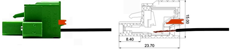
External and Internal Construction
Connecting Your Dashcam to the Power Bank – Cigar Mode
There are multiple supported connection methods. Below is Method 1 – Standard (Simplest). This method uses a cigarette lighter socket adapter and is the fastest way to connect your dash camera.
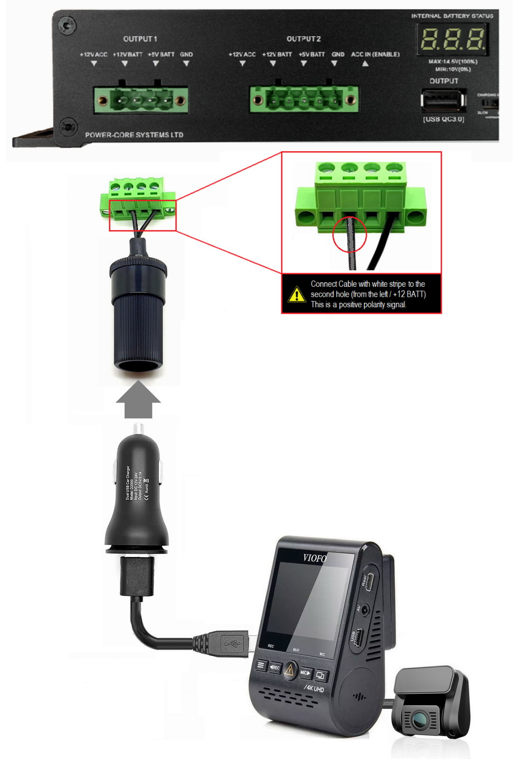
OUTPUT 2 includes an additional 5th pin (ACC IN). This optional pin can be connected to a +12V ACC signal to enable charging mode control, as described earlier.
- Incorrect connection will not damage the power bank or dash camera.
- Connectors are physically keyed – incorrect insertion is not possible.
- 4-pin and 5-pin connectors are not interchangeable.
Direct Dashcam Hardwire Connection
Method 2 – Hardwire Connection is the recommended installation method for dash cameras that support dedicated hardwire accessories. This method provides the most reliable connection and enables proper parking mode operation when the vehicle is parked.
Please follow the diagram carefully to avoid incorrect wiring. A dedicated dashcam hardwire cable is required. Before connecting the plug to the power bank, always connect and verify the wires inside the green terminal plug first.
For correct terminal assembly, see How to Secure Cable in Plug Terminal.
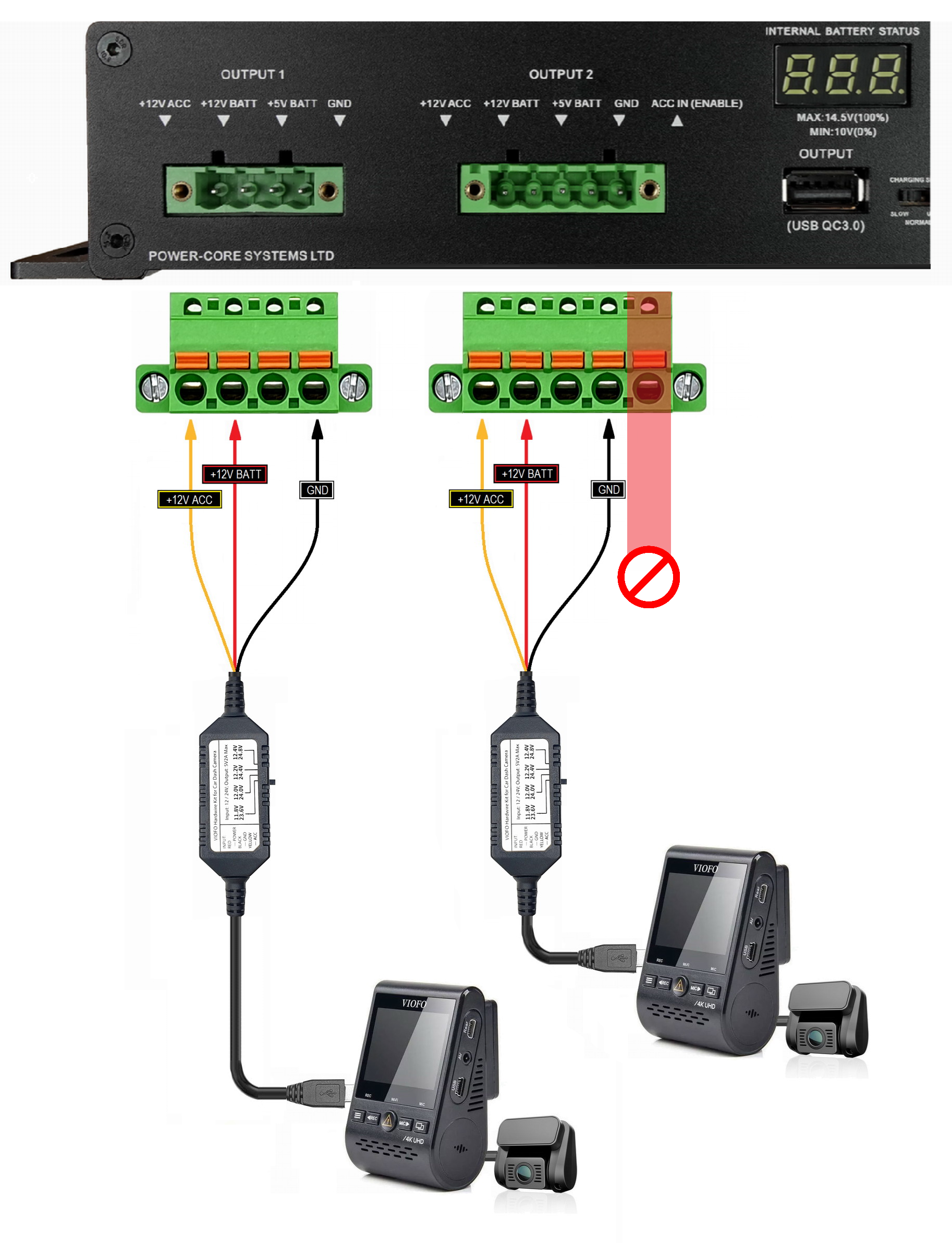
Supported Hardwire Cable Types
2-Wire Hardwire Cable
- Connect to +12V BATT and GND terminal holes.
- Typical wiring: Black = GND, Red = +12V.
- Parking mode behavior depends on the dashcam model and hardwire module design.
3-Wire Hardwire Cable
- Black = GND
- Red = +12V BATT
- Yellow = +12V ACC
- This is the preferred method for full parking mode support on compatible dash cameras.
Dual Output and OUTPUT 2 Information
Dual Dashcam Support
- A second dash camera can be connected to OUTPUT 2 in the same way.
- This allows two independent camera systems to be powered from the same power bank.
- Both outputs support parking mode when connected correctly.
OUTPUT 2 – Additional Pin
- OUTPUT 2 includes an additional 5th pin (ACC IN).
- This optional pin may be connected to a +12V ACC signal to control charging mode.
- See Installation Guidelines for ACC input details.
Use the correct dedicated green terminal plug for each output. OUTPUT 1 and OUTPUT 2 use different plug formats, and the connectors are physically keyed to reduce installation errors.
- Always verify polarity (+ / –) before connecting the system.
- Connecting GND to a positive terminal may damage the dash camera or the hardwire module.
- Incorrect RED / YELLOW assignment may prevent parking mode from working correctly.
- Never rely on wire color alone — always check cable labels and manufacturer markings.
Dashcam Connection – 5V Mode
Method 3 – USB Mini / Micro Dashcams Only. This connection method is intended only for dash cameras or other output devices that require a stable 5V DC supply through a direct USB Mini or USB Micro connection.
This option is intended primarily for advanced users and for devices that are designed to operate directly from 5V, without using a separate 12V-to-5V cigarette charger or external DC/DC converter.
By supplying regulated 5V directly from the power bank, this method can reduce conversion losses associated with typical car chargers and improve the overall efficiency of the system.
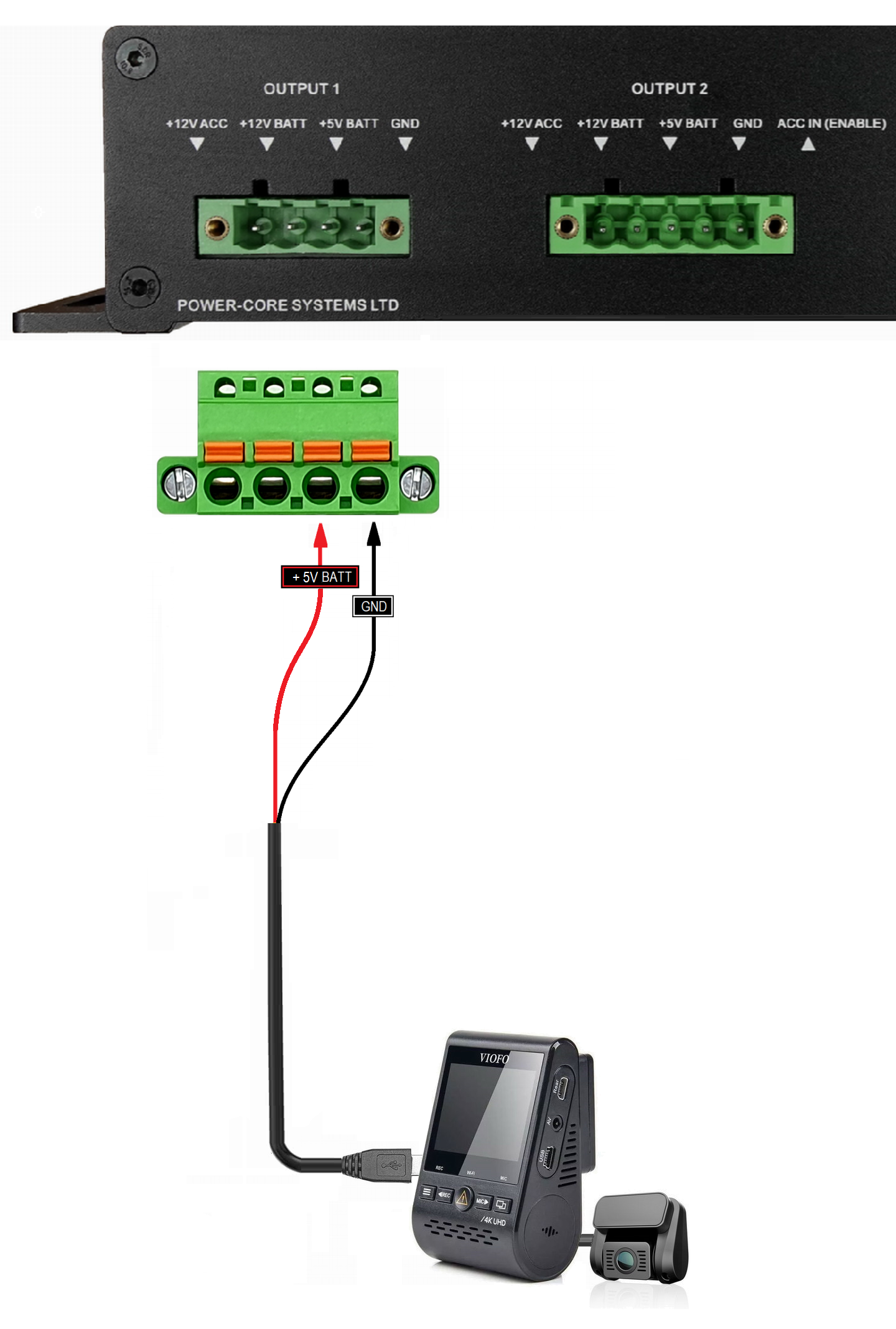
Why Use Direct 5V Mode?
Purpose of This Connection
- Designed for devices that require a direct 5V power standard.
- Useful for dash cameras that operate from USB Mini or USB Micro without a 12V charger module.
- Suitable for specific 5V accessories and dedicated low-voltage output devices.
Efficiency Advantage
- Bypasses many external 12V-to-5V charger adapters.
- Reduces power losses generated by typical DC/DC cigarette chargers.
- Allows the power bank to deliver regulated 5V directly, using stored energy more efficiently.
Connection Requirements
Before Connecting
- Ensure the camera power input requires stable 5V DC.
- Use a high-quality cable. Recommended range: AWG 13–24.
- Do not convert unknown PC USB data cables into power leads without testing them first.
- Always verify cable polarity with a multimeter before installation.
USB Verification
- Use continuity mode or diode test mode to confirm the USB pin mapping.
- Identify the actual +5V and GND conductors according to the connector pinout.
- Never rely on wire color alone.
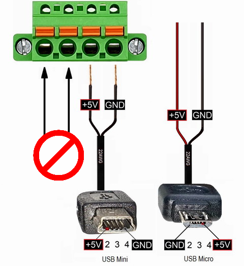
Always verify USB Mini / Micro pin polarity before connection. Incorrect polarity may permanently damage the device.
- Incorrect USB polarity may permanently damage your dash camera.
- Cable colors do not always indicate polarity correctly.
- Although red is typically +5V, this is not guaranteed.
- Always confirm voltage and pinout using a multimeter before connection.
- Never connect USB-powered dash cameras to +12V ACC.
- Never connect USB-powered dash cameras to +12V BATT.
- Doing so may instantly and permanently damage the device.
The same 5V connection method may also be used on OUTPUT 2. However, note that OUTPUT 2 uses a 5-pin terminal format, where the rightmost pin is the optional ACC IN pin. This pin is not required for direct 5V dash camera power connection.
Faults & LED Symptoms
LED indicators may behave differently depending on system state, charging phase and installation conditions.
This section explains non-obvious or unusual LED behaviors that may occur during operation. These behaviors are often part of normal system logic, but in some cases may indicate incorrect installation.
- No LED should be ON when the vehicle engine is turned OFF.
- The only exception is the REGEN LED (green), when REGEN is correctly connected and active.
- If any other LED remains ON with engine OFF, the installation may be incorrect.
- This may lead to unintended vehicle battery discharge.
- Always verify this behavior after installation and periodically.
Charging Active When Engine OFF
- If CHARGING or POWER LED is ON when engine is OFF, installation is incorrect.
- The most common cause is incorrect or missing ACC (charge enable) connection.
- Disconnect the power bank immediately.
- Reconnect ACC wire according to Installation Guidelines.
Battery Protection Behavior
- Charging stops automatically when voltage drops to approx. 11.5V.
- This protects the vehicle battery from deep discharge.
- Charging is only enabled when +12V ACC signal is present.
- This is a two-layer protection system against incorrect installation.
Fault Indication
RED LED – Fault Condition
- Indicates a serious wiring or operating fault.
- Most commonly caused by incorrect wiring or reversed polarity.
- Especially critical if REGEN polarity is connected incorrectly.
- An audible alarm may be triggered.
- Disconnect the system immediately and verify wiring.
Normal Charging Behavior
Charging / FULL LED Blinking Alternately
- This is a normal behavior, especially near the end of charging.
- The power bank manages two internal battery sections.
- The system may switch between sections to balance them.
- This may appear as alternating CHARGING and FULL LED blinking.
- After a short time (typically 5–10 minutes), FULL LED will remain ON.
Some LED behaviors may appear unusual during operation. In most cases, these are part of normal battery management and protection logic. Only persistent abnormal states (such as charging when engine is OFF or RED LED activity) should be treated as a fault condition.
Extended Battery
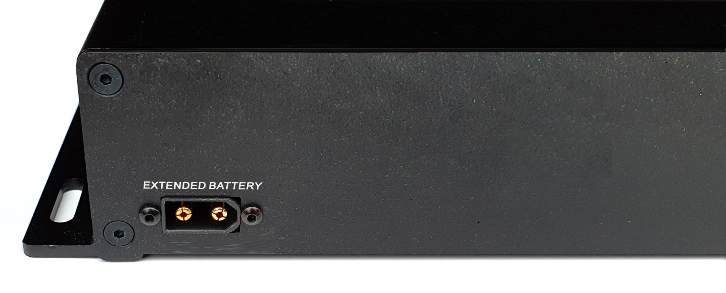
Dedicated XT60 extension port for compatible external LiFePO₄ battery modules.
The Power Core 22000LFP supports connection of a compatible external LiFePO₄ extension battery module. This allows the total system capacity to be increased by connecting a dedicated extension pack to the rear Extended Battery port.
The extension battery is connected using the dedicated cable supplied with the compatible battery module. The connection is made on the rear side of both units using the dedicated XT60 extension port.
When an external module is connected, total charging time increases in proportion to the added battery capacity.
Benefits of the Extension Battery
Why Use It?
- Expands the total usable system capacity.
- Extends dash camera runtime during parking mode.
- Useful for long parking sessions or higher-power camera systems.
System Behavior
- The system automatically balances voltage between the main unit and the extension module.
- Charging time increases according to the total combined capacity.
- A full recharge cycle may be required after installation for best performance and accurate calibration.
Installation Procedure
Once connected, the system automatically balances voltage levels between the internal battery pack and the external extension module during normal operation and charging.
- Use only compatible external LiFePO₄ extension battery modules.
- Use only the dedicated extension cable supplied with the extension battery pack.
- Do not connect unknown battery packs or external power sources to the Extended Battery port.
- Incorrect connection may cause malfunction, battery imbalance or permanent damage.
Device Maintenance
Battery Care
- Use the power bank regularly to maintain battery performance.
- Avoid leaving the device fully discharged for more than 6 months.
- If stored for an extended period, recharge the unit fully before reuse.
Temperature & Environment
- Avoid temperatures above 60°C.
- Install the unit in the coolest practical area of the vehicle, such as under a seat or inside the boot.
- Do not install the device inside the engine bay.
- Avoid direct sunlight exposure.
- Charging is automatically disabled below 0°C.
- Avoid water, condensation and excessive moisture.
Cable Safety
- Ensure cables do not interfere with airbag systems or moving vehicle components.
- Secure all cables firmly to prevent vibration movement.
- Avoid routing cables across sharp edges.
- If installed under a seat, ensure seat rails cannot trap, crush or cut the wires.
Product Warranty Card

Thank you for choosing our product. The warranty period is valid for 24 months from the date of purchase.
Services Included at No Extra Cost
- Repair of manufacturing or material defects during the warranty period.
- A valid serial number is required.
- Proof of purchase and seller details may be required.
Chargeable Services
- Invalid, missing or damaged serial number.
- Incomplete or incorrect warranty card information.
- Damage caused by improper installation, misuse or unauthorized modification.
- Water damage or mechanical damage.
- Damage caused by force majeure events (fire, flood, lightning, etc.).
- Use contrary to the instructions provided in this manual.